|
Da Vinci Firmware 1
Firmware for the DaVinci-M rocket avionics board.
|
|
Da Vinci Firmware 1
Firmware for the DaVinci-M rocket avionics board.
|
Functions to connect LIS2MDL driver to STM32H7xx SPI HAL. More...

Functions | |
| static int32_t | platform_spi_write (void *handle, uint8_t reg, const uint8_t *bufp, uint16_t len) |
| Write data to LIS2MDL sensor via SPI. | |
| static int32_t | platform_spi_read (void *handle, uint8_t reg, uint8_t *bufp, uint16_t len) |
| Read data from LIS2MDL sensor via SPI. | |
| int32_t | lis2mdl_init (stmdev_ctx_t *ctx) |
| Initialize the LIS2MDL sensor. | |
| int32_t | lis2mdl_init_2 (stmdev_ctx_t *ctx) |
Functions to connect LIS2MDL driver to STM32H7xx SPI HAL.
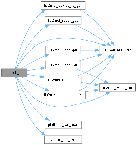
| int32_t lis2mdl_init | ( | stmdev_ctx_t * | ctx | ) |
Initialize the LIS2MDL sensor.
| ctx | Sensor context with SPI handle and platform functions |
| 0 | if OK, -1 if error or WHO_AM_I mismatch |
Definition at line 1461 of file lis2mdl_reg.c.
References lis2mdl_cfg_reg_c_t::bdu, lis2mdl_cfg_reg_c_t::ble, lis2mdl_cfg_reg_a_t::comp_temp_en, lis2mdl_cfg_reg_c_t::drdy_on_pin, stmdev_ctx_t::handle, hspi2, lis2mdl_cfg_reg_c_t::i2c_dis, lis2mdl_cfg_reg_c_t::int_on_pin, lis2mdl_boot_get(), lis2mdl_boot_set(), LIS2MDL_CFG_REG_A, LIS2MDL_CFG_REG_C, LIS2MDL_CONTINUOUS_MODE, lis2mdl_device_id_get(), LIS2MDL_HIGH_RESOLUTION, LIS2MDL_ID, LIS2MDL_LSB_AT_LOW_ADD, LIS2MDL_ODR_10Hz, lis2mdl_read_reg(), lis2mdl_reset_get(), lis2mdl_reset_set(), LIS2MDL_SPI_4_WIRE, lis2mdl_spi_mode_set(), lis2mdl_write_reg(), lis2mdl_cfg_reg_a_t::lp, lis2mdl_cfg_reg_a_t::md, NULL, lis2mdl_cfg_reg_a_t::odr, platform_delay, platform_spi_read(), platform_spi_write(), stmdev_ctx_t::read_reg, lis2mdl_cfg_reg_a_t::reboot, lis2mdl_cfg_reg_c_t::self_test, lis2mdl_cfg_reg_a_t::soft_rst, and stmdev_ctx_t::write_reg.
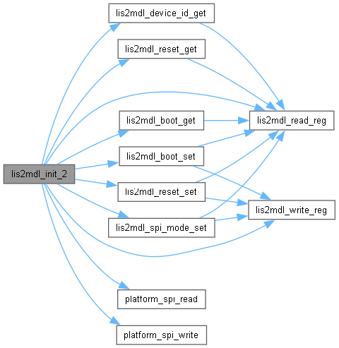
| int32_t lis2mdl_init_2 | ( | stmdev_ctx_t * | ctx | ) |
Definition at line 1556 of file lis2mdl_reg.c.
References lis2mdl_cfg_reg_c_t::bdu, lis2mdl_cfg_reg_c_t::ble, lis2mdl_cfg_reg_a_t::comp_temp_en, lis2mdl_cfg_reg_c_t::drdy_on_pin, stmdev_ctx_t::handle, hspi3, lis2mdl_cfg_reg_c_t::i2c_dis, lis2mdl_cfg_reg_c_t::int_on_pin, lis2mdl_boot_get(), lis2mdl_boot_set(), LIS2MDL_CFG_REG_A, LIS2MDL_CFG_REG_C, LIS2MDL_CONTINUOUS_MODE, lis2mdl_device_id_get(), LIS2MDL_HIGH_RESOLUTION, LIS2MDL_ID, LIS2MDL_LSB_AT_LOW_ADD, LIS2MDL_ODR_10Hz, lis2mdl_read_reg(), lis2mdl_reset_get(), lis2mdl_reset_set(), LIS2MDL_SPI_4_WIRE, lis2mdl_spi_mode_set(), lis2mdl_write_reg(), lis2mdl_cfg_reg_a_t::lp, lis2mdl_cfg_reg_a_t::md, NULL, lis2mdl_cfg_reg_a_t::odr, platform_delay, platform_spi_read(), platform_spi_write(), stmdev_ctx_t::read_reg, lis2mdl_cfg_reg_a_t::reboot, lis2mdl_cfg_reg_c_t::self_test, lis2mdl_cfg_reg_a_t::soft_rst, and stmdev_ctx_t::write_reg.
|
static |
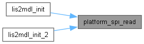
Read data from LIS2MDL sensor via SPI.
| handle | Pointer to SPI_HandleTypeDef (passed via stmdev_ctx_t) |
| reg | Register address to read from |
| bufp | Pointer to data buffer to store read data |
| len | Number of bytes to read |
| 0 | if OK, -1 if error |
Definition at line 1418 of file lis2mdl_reg.c.
References HAL_OK, LIS2MDL_CS_GPIO_Port, LIS2MDL_CS_Pin, LIS2MDL_SPI_TIMEOUT, and NULL.
Referenced by lis2mdl_init(), and lis2mdl_init_2().
|
static |
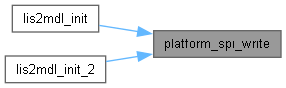
Write data to LIS2MDL sensor via SPI.
| handle | Pointer to SPI_HandleTypeDef (passed via stmdev_ctx_t) |
| reg | Register address to write to |
| bufp | Pointer to data buffer to write |
| len | Number of bytes to write |
| 0 | if OK, -1 if error |
Definition at line 1372 of file lis2mdl_reg.c.
References HAL_OK, LIS2MDL_CS_GPIO_Port, LIS2MDL_CS_Pin, LIS2MDL_SPI_TIMEOUT, and NULL.
Referenced by lis2mdl_init(), and lis2mdl_init_2().