Onboarding: Presenting the work and process of the firmware division of the Polito Rocket Team
🚀 A Note to the New Team
Welcome to the Firmware sub-team! Whether you’re a seasoned embedded developer or just starting, you are now part of the rocket’s central nervous system. The code you write is responsible for:
- Data acquisition from all sensors
- Flight state determination
- Triggering critical events like parachute deployment
- Active control of the airbrakes
- Telemetry to the ground station
- GPS tracking
This is a very challenging but incredibly rewarding role. This document is your starting point—a recap of everything we’ve learned, built, and planned. Read it carefully, ask questions, and don’t be afraid to challenge old assumptions. The goal isn’t just to maintain what we have, but to make it better.
Good work!
Part 1: Onboarding & Core Knowledge
This section contains the fundamental knowledge you need to get started.
1.1. Our Mission & Philosophy
-
Safety is Paramount: Our code controls safety-critical systems like the parachutes and airbrakes. An error in timing or logic can have catastrophic outcomes. Every line of code, even for non-critical features, must be written and reviewed with a safety-first mindset.
-
Data is King: We fly to learn. The Davinci’s core task is to reliably collect high-quality data. Our current system acquires accelerometer data every 25 microseconds and all other data every 10 milliseconds. This high-fidelity data is a unique capability that provides the Mission and Control Analysis (MSA) team with an invaluable resource.
- Test, Test, and Test Again: We practice iterative development: build small, test thoroughly on the ground, and then integrate. A feature that hasn’t been ground-tested does not fly. We perform “choral tests”—progressively integrating more hardware to simulate flight conditions. This includes:
- Connecting Davinci and Marconi boards and monitoring their interaction.
- Connecting a Marconi to actuators (e.g., servomotors) to verify physical responses.
- Using debuggers, LEDs, flash logs, and telemetry to validate behavior at every stage.
- Keep It Simple (KISS Principle): A complex system has more failure points. We strive for the simplest, most robust solution to satisfy requirements. Designing with simplicity and scalability in mind allows us to add new features in the future without a complete system overhaul.
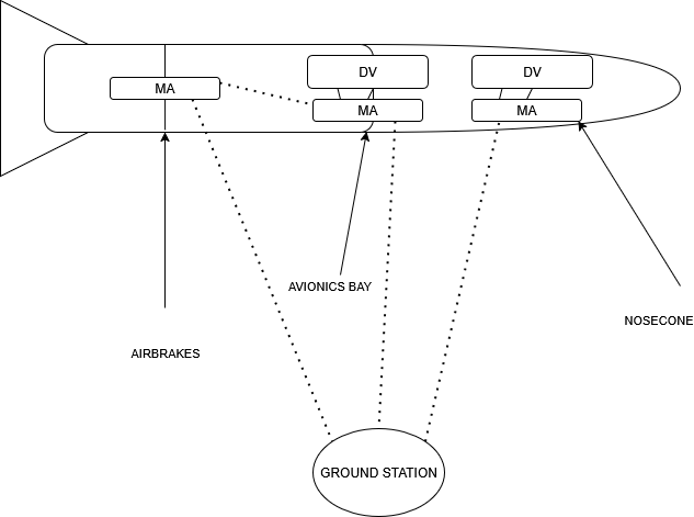
1.2. System Architecture Overview
Our avionics system consists of two main types of custom boards: the Davinci (the central flight computer) and the Marconi (the telemetry and local control board).
Davinci Flight Computer (FC)
Located in the nosecone and avionics bay, the Davinci is the primary “brain” of the rocket—a powerhouse responsible for all critical computations, state estimation, and control algorithms.
- Microcontroller (MCU):
STM32H743VITx - Sensors (SPI Bus):
- IMU:
LSM6DSO32(Inertial Measurement Unit for linear and rotational acceleration) - Barometer:
BMP390(Pressure and Temperature) - Magnetometer:
LIS2MDL
- IMU:
- Actuators:
- Pyro Channels: MOSFET-controlled channels for parachute deployment e-matches.
- Buzzer/LEDs: Status indication.
- On-Board Communication:
- USART: Wired communication with a Marconi board.
- Data Storage:
- QuadSPI Flash:
W25Q512JV(512 Mbit)
- QuadSPI Flash:
- Ground Communication:
- USB/Serial: For data offload on the ground.
- UART: For debugging, data extraction, and flashing.
Marconi Telemetry & Control Board
Located in three separate compartments (nosecone, avionics bay, and airbrakes), the Marconi acts as the rocket’s nervous system, handling communications, GPS, and local actuator control.
- Microcontroller (MCU):
STM32F413RGTx - Sensors:
- Primary (SPI2):
LSM6DSO32IMU - Backup (SPI3)
- GNSS:
TESEO LIV3FL(GPS)
- Primary (SPI2):
- Actuators:
- Buzzer/LEDs: Status indication.
- PWM GPIO: Control of servomotors for airbrakes.
- On-Board Communication:
- USART: Wired communication with a Davinci board.
- XBEE Radio:
900HP/XSCfor wireless communication between Marconis (e.g., AVN bay to Airbrakes).
- Data Storage:
- EEPROM:
24LC512-I/SMused for storing a unique ID for each Marconi.
- EEPROM:
- Ground Communication:
- LoRa Radio:
E220for telemetry downlink and command uplink with the Ground Station. - UART: For debugging and flashing.
- LoRa Radio:
1.3. Getting Your Development Environment Ready
- Version Control (Git): All code is hosted on GitHub.
- Davinci: https://github.com/PoliTo-Rocket-Team/DaVinci-Nosecone
- Marconi: https://github.com/PoliTo-Rocket-Team/Marconi-Nosecone
- Workflow:
- Clone the repo:
git clone [URL] - Create a feature branch:
git checkout -b feature/my-new-feature - Make your changes and commit them.
- Open a Pull Request (PR) to merge your feature branch into
mainordevelop. Never push directly to the main branch.
- Clone the repo:
- Toolchain & IDE:
- IDE:
STM32CubeIDE - Programmer:
STM32CubeProgrammer - The required ARM-GCC toolchain is included with STM32CubeIDE.
- IDE:
1.4. The Codebase: A Guided Tour
Davinci Codebase (Davinci_2 project)
The repository contains projects for both old (F411) and new (H743) hardware. You will be working in the Davinci_2 project. The code is organized as follows:
Inc/: Header files (.h).Src/: Source files (.c).Davinci_2.ioc: The STM32CubeMX configuration file. This file is critical. It defines pinouts, clock configurations, and peripheral settings, and it auto-generates initialization code.
The source files (Src/) can be categorized into:
- Drivers: Low-level files for interacting with specific hardware components (e.g.,
lsm6dso32_driver.c). - Controllers: High-level logic files (e.g.,
kalmanFilter.c,FSM.c). - Auto-Generated Code: Code generated by CubeMX, found in
main.cand peripheral files (usart.c,spi.c, etc.).
Marconi Codebase
The structure is similar, centered around the Marconi.ioc file. The code is primarily a mix of drivers and auto-generated peripheral handlers.
1.5. Core Firmware Concepts and Features
-
RTOS & DMA: We use a Real-Time Operating System (FreeRTOS) to manage multiple tasks concurrently. To maximize CPU availability for computation, most data transfers (e.g., SPI, UART) are handled by the Direct Memory Access (DMA) controller, which works independently of the CPU.
-
Integration inside the rocket: In the rocket we place various versions of our boards, in order for them to complete different tasks, to do so we divide the rocket in 3 areas, the nosecone, the top of the rocket, the avionics bay, our brain, and the airbrakes, located close to our brakes dispositive. The avnbay area is equipped with our most sophisticated material, a complete Marconi-DaVinci duo, with the Marconi also equipped with an XBEE that communicates with the airbrakes area, which is only containing a single Marconi, connected to the servomotor that controls the brakes, eventually in the nosecone there is also a Davinci-Marconi duo but not equipped with an XBEE.
-
Turn-on Melody: To confirm that onboard systems are active, the buzzer on each board plays a unique short melody at startup. This allows the launch crew to audibly distinguish between the Davinci and Marconi boards when they power on inside the rocket.
-
Flight State Machine (FSM): The rocket’s flight is modeled as a sequence of states. The FSM transitions between states based on sensor data. To prevent false triggers from noise, a transition only occurs if a condition is met for a certain number of consecutive checks. The diagram below illustrates the flight profile and the corresponding states.
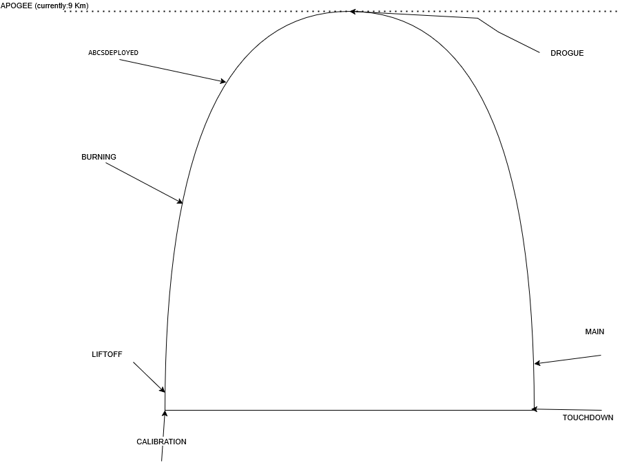
INVALID: Error state, currently unused.CALIBRATION: Initial state on power-on.LIFTOFF: Triggered by Z-axis acceleration > 6g OR altitude > 20m (backup).BURNING: Reached at 5 km altitude. Kalman filter is activated.ABCSDEPLOYED: Reached at 7 km altitude. Airbrakes controller is activated.DROGUE: Triggered after apogee (highest point) is detected (3 consecutive lower altitude readings). Drogue parachute is deployed. Kalman and Airbrakes controllers are deactivated.MAIN: Triggered when altitude drops below 450m during descent. Main parachute is deployed.TOUCHDOWN: Final state, triggered below 20m altitude.- Apogee Safety Check: If an apogee event is detected before reaching 7 km, the FSM transitions directly to
DROGUEto ensure parachute deployment.
- Data Packet Structures: We use custom binary packets for efficient data transfer.
-
DV-MPacket (Davinci to Marconi): Sent every 10ms.Field Size (Bytes) Description Linear Accel (X,Y,Z) 12 3 floats from IMU Gyro Accel (X,Y,Z) 12 3 floats from IMU Magnetometer (X,Y,Z) 12 3 floats from Mag Temperature 4 float from Baro Pressure 4 float from Baro Altitude 4 float from fusion/baro Velocity 4 float from fusion/GPS Flight Phase 1 uint8_t of FSM state Davinci Battery 4 float voltage Airbrakes Degrees 4 float controller output Drogue Flag 1 bool deployment status Main Flag 1 bool deployment status Total ~63 Bytes -
M-GSPacket (Marconi to Ground Station): Sent every second. Contains the fullDV-Mpacket plus Marconi-specific data.Field Size (Bytes) Description Header ~1 Start of Packet Marconi ID 1 ‘P’ (Airbrakes), ‘A’ (AVN), ‘D’ (Nosecone) … (all DV-M data) ~63 Longitude 4 float from GNSS Latitude 4 float from GNSS Marconi Battery 4 float voltage Footer !1 End of Packet Total ~78 Bytes
-
-
Marconi Distinction System: To use a single firmware for all three Marconis, we write a unique ID (‘p’, ‘A’, or ‘D’) to the onboard EEPROM during initial setup. On startup, the Marconi reads this ID into a global variable. The firmware then uses
if/elselogic based on this ID to perform its specific role (e.g., only the Airbrakes Marconi listens for XBEE commands; only the Nosecone and AVNbay Marconis send LoRa telemetry). - Flash Data Storage (Davinci): To optimize flash writes, we buffer data before saving.
- Linear acceleration (12 bytes) is sampled every 25 µs.
- All other data is sampled every 10 ms.
- Since 10 ms = 400 * 25 µs, we save the “other data” packet once for every 400 linear acceleration samples.
- To minimize DMA access frequency, we fill a large buffer in RAM before triggering a single, large write operation to the QuadSPI flash.
- Ground Station (GS) Communication: The Marconi can receive 3-byte commands from the GS via LoRa.
- Channel Change: Send
'F' + [digit_1] + [digit_2]. The two bytes after ‘F’ are the ASCII characters for the channel number. For channel 07, send'F', then the ASCII byte for'0', then the ASCII byte for'7'. - Camera On: Send
'X' + [any_byte] + [any_byte]. - An acknowledge system exists in the firmware but is currently disabled pending GS updates.
- Channel Change: Send
- Airbrakes Cross-Communication (XBEE):
- The Davinci runs the airbrakes control algorithm and calculates the required servo angle (degrees).
- This degree value is sent via UART to the AVN Bay Marconi.
- The AVN Bay Marconi broadcasts this value via its XBEE radio.
- The Airbrakes Marconi receives the value on its XBEE, converts it to a PWM signal, and drives the servomotor.
1.6. How to Work with Other Divisions
- Firmware Division (Hardware & Telemetry): You will work very closely with the hardware designers and telemetry specialists within our division. Communication should be constant and open.
- Other Divisions (MSA, Controls): You are a service provider for teams like Mission & Control Analysis (MSA). Be proactive, available, and precise in your interactions. Your collaboration is key to the project’s success. When you need to interact, it’s best to contact the relevant division lead or the specific person working on the feature you need.
1.7. How to Succeed in the Team
-
Team Structure: The PoliTo Rocket Team has three main branches: Rocket (which you are in), EFESTO (our engine development), and Operations (HR, media, etc.). Within the Rocket branch, we are organized into divisions, each led by a lead like myself.
-
Mindset and Responsibility (“Nemo Nos Salvabit”):
- Ownership: This team operates like a startup. You take full ownership of your work. There are no grades or perfect corrections; launch day is the exam, and a successful mission is the only passing grade.
- Proactivity: The difficulty of your tasks is set by the project’s needs, not your current skill level. You will be challenged. You must be proactive in learning and problem-solving.
- Accountability: While myself and other advisors can offer guidance, we will be remote. The responsibility for implementing, testing, and verifying the firmware rests with you. Always think: “What could go wrong, and how can I prevent it?”
Part 2: Resume of 2024/2025
2.1. Major Accomplishments
- New Hardware Design: Designed, produced, and validated two completely new boards (Davinci H7, Marconi F4), migrating from weaker processors to enable advanced computational capabilities.
- Enhanced Sensing: Integrated a magnetometer and a much larger W25Q512 flash on the Davinci.
- Kalman Filter Implementation: Upgraded from simple barometric readings to a robust Kalman filter for significantly improved state estimation.
- New External Loader: Developed a custom external loader for the STM32H7, enabling data dumping from the new QSPI flash.
- Automated Data Parsing: Wrote Python scripts to parse the binary data dump and generate structured Excel files for analysis.
- New Telemetry System: Deployed a new Ground Station application with upgraded LoRa modules and antennas, supporting higher data throughput.
2.2. Key Design Decisions & Rationale
- MCU Choice (
STM32H743VITx): Selected for its high clock frequency (480 MHz), Floating Point Unit (FPU), and multiple DMA controllers, which are essential for handling our numerous high-throughput tasks simultaneously. - Flash Choice (
W25Q512): A simple upgrade from the previous W25Q128. This provided the required 512 Mbit capacity for high-frequency data logging while minimizing changes to the hardware layout and firmware drivers.
2.3. Lessons Learned
- Reading Datasheets is Painful but VITAL: Do not delegate datasheet reading to AI or skim through it. Every new component integration must start with a thorough, manual review of its datasheet. Small misunderstandings can lead to weeks of debugging.
- Be “Pessimistic” with Time Management: Hardware issues, obscure bugs, and design flaws are inevitable. Always build significant buffer time into your development schedule.
- Design for the User (the Launch Crew): The firmware and hardware must be reliable, ergonomic, and easy to operate under pressure on launch day. Features like status LEDs, buzzers, and plug-and-play operation are not luxuries; they are essential for mission success.
Part 3: Roadmap for 2025/2026
This is our vision for the future. It’s a list of goals and tasks for you to tackle.
3.1. Bug Fixes & Testing
- Investigate Spontaneous Airbrake Opening:
- Symptom: The airbrakes were observed to open slightly upon power-on at the launch site, before the
ABCSDEPLOYEDstate. - Hypothesis: The issue could be a hardware mounting offset or an uninitialized variable in the firmware. Since the control algorithm isn’t running at startup, the initial
degvariable in either the Davinci or the Airbrakes Marconi might contain a garbage value. - Task: Recreate the setup (Davinci, Marconi, Servo, Airbrakes). Power it on and observe. If the issue persists, trace the
degvariable from its initialization on both boards to the PWM signal generation. Ensure it is explicitly initialized to0.
- Symptom: The airbrakes were observed to open slightly upon power-on at the launch site, before the
- Analyze LoRa Frequency Change Delay:
- Symptom: Changing the LoRa channel via GS command takes exactly 5 minutes to take effect.
- Hypothesis: The E220 module’s datasheet suggests this should be nearly instantaneous. The delay might be caused by an unintentional blocking loop, a long timeout, or a misconfiguration in our driver.
- Task: Investigate the E220 driver code and the command handling logic on the Marconi. Trace the execution flow after a channel change command is received.
- Resolve Intermittent IMU Calibration Issues:
- Symptom: On startup, the magnitude of the acceleration vector (
sqrt(ax^2 + ay^2 + az^2)) is sometimes not equal to ~1000 mg (1g), indicating a calibration offset. The issue is inconsistent across boards and power cycles. - Hypothesis: This could be related to timing (reading sensor values before it’s fully stable), a software bug in the calibration procedure, or a hardware-specific issue.
- Task: Systematically test all Davinci boards. Log how often the issue occurs on each. Investigate the IMU startup sequence and calibration code. Check if a delay after power-on or a reset of the sensor fixes the issue.
- Symptom: On startup, the magnitude of the acceleration vector (
- Verify QSPI Flash Mode-Switch Stability:
- Symptom: The flash memory datasheet warns of a potential crash when switching from Memory-Mapped (MM) mode to Normal mode. Our workflow (Normal flight -> MM data extraction) triggers this condition.
- Hypothesis: The flash may not be restarting correctly after data extraction, potentially corrupting subsequent flights.
- Task:
- Create a clear test procedure: Run a normal power-on, read the flash with the External Loader (which uses MM mode), then immediately restart the board in normal flight mode.
- Use LEDs and a logic analyzer to verify that the board restarts correctly and that new data is logged properly.
- If the bug is confirmed, integrate the potential fix from the
apply_erratabranch (commit5ab6e42) and re-run the test procedure to validate the fix.
3.2. New Features & Improvements
- Implement USB Data Extraction:
- Goal: Replace the current 16-minute External Loader process with a faster USB-based solution.
- Task: Implement the Davinci as a USB Mass Storage Device. A previous attempt was made, but abandoned. You can build on this work. Note: The existing flash drivers rely on DMA, which cannot be used in the standard USB library’s ISR context. You will need to write new, non-DMA-based flash read functions for the USB data transfer.
- Advanced Data Visualization (Pandas):
- Goal: Move beyond basic Excel plots and provide more sophisticated, automated analysis tools for the MSA team.
- Task: Collaborate with the MSA team to understand their needs. Use the Python Pandas library to create scripts that generate advanced plots, perform statistical analysis, and create flight summary dashboards from the data dump.
- Implement the
INVALIDFSM State:- Goal: Make the state machine more robust by adding error handling.
- Task: Define conditions that would lead to an
INVALIDstate (e.g., conflicting sensor readings, failed state transition). Implement the logic and decide what action the rocket should take in this state (e.g., enter a safe mode, log the error).
- Implement a Watchdog System for Sensor Redundancy:
- Goal: Automatically detect sensor failures and switch to backup systems.
- Task: Use the STM32’s built-in watchdog timers or a software equivalent to monitor the health of the primary SPI sensors. If a sensor (e.g., the primary IMU on SPI2) stops responding, the firmware should automatically switch to using the backup sensor on SPI3.
- Reinstate and Expand the GS Acknowledge System:
- Goal: Create a more reliable command link with the ground station.
- Task: The code for this largely exists. Re-enable it and test it thoroughly with the GS team. Expand it to cover more commands and provide more detailed feedback (e.g.,
ACK_SUCCESS,NACK_INVALID_COMMAND).
Useful Resources
- Our Wiki: https://wiki.politorocketteam.it/index.php/Main_Page
- Google Drive (All Datasheets): https://drive.google.com/drive/folders/17yADMzwVpnjHh9fwa1LZ1kRZlPu9dl5W
- Beginner’s Guide to Git: https://www.analyticsvidhya.com/blog/2020/05/git-github-essential-guide-beginners/
- Excellent RTOS Blog Series: What is a Real-Time Operating System (RTOS)?
Good luck, and feel free to reach out with any questions.
Francesco Abate
- Email:
francesco1.abate@yahoo.com - Discord: Tag me in the group.